


SHOP TALK: Modern Diagnostics & New Scan Tool
- 908 Motorsports Magazine
- 6 days ago
- 9 min read
Written by: JT Photos by: JT
Hello fellow gearheads. As always, I pray this finds you all happy, healthy, and enjoying some type of adrenaline pumping, high horsepower.
Winter is not quite over here in the northeast and that means the car world is still shut down and anxiously awaiting the warmer days of our late spring. It also means that it’s time to finish tinkering in the shop and make all the necessary repairs, along with the unnecessary improvements.
This past winter, besides making some repairs and improvements, I found myself addicted to learning more about modern vehicle diagnostics. I have become officially full-blown obsessed with the deep, dark, black voodoo magic world of scan tools along with ECM, BCM, PCM, function and design.
I recently completed an extensive custom job on a customer’s 2007 Mustang. I made the decision to re-invest 100% of the money into purchasing a new scan tool that can perform over 40 service functions, OEM level all-system diagnostics, auto VIN, auto scan, full bi-directional control active tests, numerous advance functions, and the icing on the cake is it’s Bluetooth. So that means no cable is needed from the vehicle to the tablet. This feature will work from up to 33 feet away from the vehicle making it easy to sit at the comfort and convenience of my workbench and perform all functions.
I really like the shop and customer sections of the scan tool as well. I can save all customer data, and print out pre and post scan reports wirelessly all on a professional and detailed letterhead with my shop logo and info.


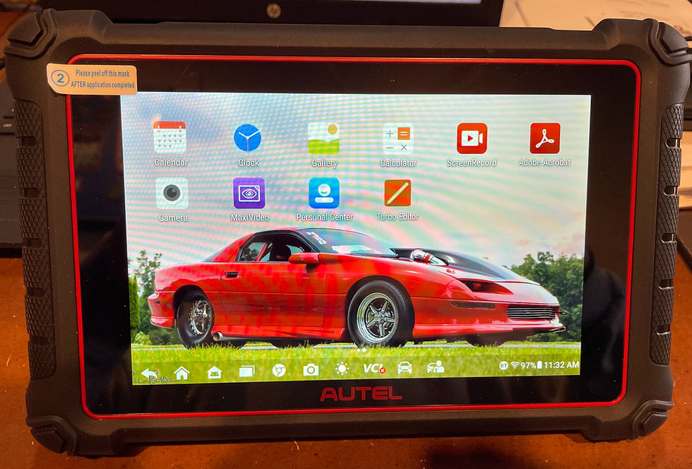
A few of the pages and features my new scan tool has. I love that
I was able to customize the home screen with a picture of Big Red.
Upon receiving my new scan tool, I read the 100-plus page manual front to back a few times to familiarize myself with my latest investment. I remember plugging it in for the first time and feeling so inadequate. I immediately knew I needed more knowledge. My knowledge of electronics is expert level and is actually one of my specialties. However, I needed more knowledge of sensors and their functions. I needed to understand the difference between ECM, PCM, and BCM functions and controls.
I opened up Pandora’s Box when I turned that unit on. I quickly came to the humbling and harsh reality that I NEEDED to learn so much more. While looking through my recently opened Pandora’s Box, I stumbled upon Schrodinger’s Box. What exactly is Schrodinger’s Box you may be asking? I had the same question and asked the genius behind this incredible source if he was making fun of the hypothetical guesses Schrodinger’s Cat suggests and its correlation into automotive diagnosis. He laughed at me during one of our video conferences and said that I had a very interesting interpretation of its meaning. But not even close. So to better explain what his YouTube Channel is all about, here is his direct explanation: This channel is for Advanced DIY auto repair with the specific purpose of preventing "parts changing"- that is- changing parts on a guess because of a lack of understanding on how to test if a part is actually faulty. This is accomplished by using a methodical, scientific approach to accurately confirm a diagnosis before attempting a repair. Subscribe here and you'll stop changing O2 sensors every time you get a check engine light or waste money changing plugs and wires to try and fix a misfire. Find exactly what is causing the problem and fix it right the first time with confidence! This brief definition revealed everything I needed and wanted to learn.
Like most of my drag racing gearheads, we are already familiar with the sensors that our data loggers utilize. Sensors such as: O2, EGT, Linear actuators for shock travel, driveshaft speed, crank sensors, RPM, temp sensors, and G-Force accelerometers. We are familiar with them because we had to actually install them and learn how to read and graph the data they produce. While many of the modern car sensors function the same, there are numerous others that do a wide variety of monitoring and data capturing. Knowing where and how to find this data is only a small part of the process. Knowing how to read the data, and how it affects the vehicles performance is a completely different issue.
Matt from Schrodinger’s Box did us all a huge favor. Besides providing us with extremely detailed diagnostic videos, he managed to do this in an easy to understand and humorous delivery that connected with how my brain needs to learn new concepts. Matt’s channel has endless FREE informative videos to learn from. For the geeks like me in the world who need just a little more detail he also has a paid channel that takes advanced modern diagnostics to another level. There are a few channels like his that are worth your precious time investigating. However, I simply prefer his methods and his delivery as a human and teacher. Matt was extremely generous with his time during our video conferences helping and guiding me on my quest for knowledge. He graciously agreed to provide us all with a brief overview of the types of sensors and how to identify them. The below outlined sensor types are here to simply help us gain more knowledge and get a better understanding of the basic differences and functions. There are many variables and other circumstances that come into play here, but this is simply a “general” description.
Car Sensor types:
Potentiometer – Typically a 3-wire sensor (Reference, ground and signal) that works by measuring voltage variance from a variable resistor that changes with physical movement (often called a “sweep”). Examples- Throttle position sensor, Accelerator position sensor, and position sensors that detect solenoid positions (example EGR position sensor). Pressure sensors are also usually potentiometers where pressures will push on a diaphragm that acts as the sweep. Barometric pressure sensor, MAP sensor, fuel rail pressure and boost sensors are examples.
Thermistor – Typically a 2 wire sensor (reference voltage and ground) that changes resistance with varying temperature. Normally colder temperatures increase resistance, higher temperatures reduce resistance. PCM reads the voltage drop between a fixed resistor and the thermistor and interprets the voltage to determine the temperature by referencing a Voltage/Temperature chart. Examples: Intake Air Temp Sensor, Oil temp sensor, Transmission Temp sensor, Coolant Temp sensor. Helpful to know an open circuit on a Thermistor usually displays a temperature of -40F on a scan tool.
Piezoelectric Sensor – Typically a one-wire sensor (Voltage output, ground is engine block) but sometimes two wire (Toyotas e.g.) used to detect sound or vibration. Vibration from sound waves causes the piezoelectric crystal to generate a small voltage proportional to the vibration. Example is engine knock sensor where engine knock from pre-ignition causes the sensor to generate a voltage and ignition timing is advanced until the knock is reduced.
Hall effect/Inductive Sensors – Typically Speed or Rotational position sensors such as vehicle speed sensor, camshaft position sensor or Crankshaft position sensor. Hall effect sensors are typically 3 wire sensors (reference, ground and signal) where teeth from a magnetic reluctor wheel rotate just millimeters from the sensor and divert the reference voltage towards the signal. In the case of a camshaft or crankshaft hall effect sensor, different sized teeth on the reluctor cause longer or shorter electrical signal pulses that allow the PCM to identify the exact piston position for each cylinder so fuel and spark can be timed optimally. In the case of hall effect speed sensors, the frequency of signal is proportional to the rotational speed and thus allows the PCM to calculate data such as RPM or MPH. These sensors may be Inductive sensors instead of hall effect. Inductive sensors are typically two-wire sensors that carry an A/C voltage that is actually generated by the sensor itself as result of the reluctor wheel rotation (magnetism+motion+conductor=voltage). The amplitude and frequency of the generated voltage is proportionate to rotational speed. In rare cases, optical sensors are used in these applications- essentially a beam of light is interrupted by the reluctor wheel teeth and the pulses of light detected are proportional to the rotation.
Oxygen, Air/Fuel Sensors – Oxygen sensors are typically 4 wire sensors (2 wires for oxygen sensing, two wires for an internal 12V heater circuit) placed in the exhaust where the presence of oxygen inhibits a chemical reaction in the sensor that normally generates a voltage of .9 volts. In a typical setup, there will be an oxygen sensor located at or near the exhaust manifold upstream of the catalytic converter and another downstream of the catalytic converter. The upstream oxygen sensor detects lean (excess oxygen) or rich (lower oxygen) content of the exhaust and adjusts fuel mixture accordingly (known as fuel trim) to try to maintain an optimal fuel mixture for combustion (in most cases a 14.7:1 air:fuel ratio known as stoichiometric balance). The engine constantly optimized the air:fuel ratios slightly to optimize catalytic converter activity so a healthy engine with proper fuel balance generally oscillates between .1V and .9V causing the characteristic “sine wave” voltage pattern from the sensor. The downstream oxygen sensor is used to detect activity of the catalytic converter- a healthy catalytic converter with functional catalyst generally uses up the oxygen in the exhaust reflecting a rich condition (.9V) at most times. A catalytic converter that has expired will be unable to maintain this condition and when the rear O2 sensor detects this, it will report a catalyst inefficiency code. Typical Oxygen sensors do NOT detect degrees of oxygenation in exhaust. ANY reading under .45V is considered lean. ANY reading over .45V is considered rich. The amount of leanness or richness is not determined, thus the sensors are known as “narrow band”. This is as opposed to Air/Fuel sensors which despite also having 4 wires (two for signal generation and two for a 12V internal heating circuit) these sensors actually measure the exact balance of air:fuel mix ratio in the exhaust. A/F sensors generate signal through milliamperage in alternative polarity that is proportionate to the air:fuel ratio detected. This allows a much more precise fuel control than a narrow band sensor is capable of since the exact degree of richness or leanness is determined. Cars with A/F sensors typically have A/F sensors upstream and traditional O2 sensors downstream. In either case, O2 or A/F sensors only work in very high temperatures- typically over 600F which is why they have internal heating circuits to help them achieve this operational temperature sooner to help reduce emissions.
Matt wants to emphasize that it is critical to note that this is just an extremely general summarization of common traditional sensor strategies. Some sensors may have more or less wires than indicated. Also some sensors nowadays may work through digital signal processing sent over a network as opposed to electrical signaling.

I not only installed every sensor on my race car, I also made every bracket to mount them in place. It is a great feeling to know where and what every sensor is on my race car. I can't say the same for the engine on my new Camaro. This is what prompted me to start this crazy journey of learning about modern technology.

I realize that you were just given an intense amount of information to digest and commit to memory. This may not be for the average gearhead. However, the future of all automotive diagnostics depends upon not only a sound understanding of electronics, but thorough knowledge of a vehicle’s computer systems and the sensors it uses to collect data.
I admitted earlier that I was indeed a gearhead geek! So besides purchasing my new scan tool, I also purchased a PICO Scope interface for my laptop to enhance my signal diagnosis and give me another tool besides by DVOM to read voltage. I even purchased a bore scope that connects directly to the scan tool and provides photo and video documentation of data as well as real time analysis. But wait, there’s more! I even purchased a battery diagnostic attachment for the scan tool that performs a dealer level test with full reports. So yeah, I kind of geeked out over the winter and did my best to enhance my automotive knowledge. I am thoroughly enjoying this new chapter in my gearhead life and no longer dread seeing a modern vehicle enter my Custom Shop. I actually from time to time find a willing “donor” and plug into it just to noodle around and practice analyzing real time data and various special functions.


I told you I geeked out and purchased a bunch of new tools!
I pray that you found this feature helpful and informative. My recommendation is to subscribe to Schrodinger’s Box and become a member of Matt’s Quantum Mechanics page as well. You have two choices with the future of automotive repair. You can either run away and hide from the changes and be at the mercy of someone else, or you can embrace the new technology and continue to take care of all of your own automotive needs.
You are NEVER too old to learn something new. I became a data logger junkie with my race car in my early 50s. Prior to that I was relying on bringing an old-time racer to each event and have him watch every aspect of my pass from staging to going through the finish line. I promise you it is so much easier and more accurate to plug in your laptop and see that information on a graph. I am approaching this stage of my learning with the same enthusiasm. Knowledge is power and I seek and yearn for more.
I’m looking forward to another season of exciting car events and projects. I fully plan on completing that custom Mega Mud Truck I have been building for the past few years before next winter. That project will provide me with numerous feature articles and more helpful tips and knowledge to share.
Until next time – Keep Wrenching (and scanning lol)
JT


Comments